What's the point of a "Night Light?" :
This mod is for those people who wanna put a light in the CD drive of the Dreamcast so they can see the spindle and laser at night, so they don't accidently miss putting the CD on the spindle, and possably damanging the laser. Get that!?
Why should I do this? :
It is an easy, and fun mod to do. You get to experiment with the PSU, and might gain a better understanding of electronics.
NOTE: I'm gonna tell you right now, my original mod used 2 12v lamps. As of writing this tutorial, I replaced those 2 12v lamps with 2 2300MCD 3v LED's. Runs WAY cooler. I reccommend 2 LED's over the 2 lamps.
What you will need :
1. Soldering iron, and solder
2. Dreamcast system
3. 1 OR 2 white LED's that run approx. 3v, with no less than 1500 MCD.
4. Drill, with bits
5. Super glue
6. Phillips head screwdriver
7. Good length of thin wire, around 6 gage
8. Normally Open spring loaded switch "NO Switch" -optional --would control the LED's on - off according to if the lid is open or closed
9. Creativity
Let's begin young grasshopper :
Ok, the boring part. Remove the four screws from the bottom of the Dreamcast system. Remove top half of case.
Ok, boring part over...
Look at the PSU, it on the left. Do you see where it says...
3.3v - 5v - Gnd - Gnd - Gnd - 12v
Good. This is where we are going to pull power from to light the LED's. Now, we wanna take our LED, and wire it it. Just splice the ene of each wire, and wrap the wire around each leg of the LED's. Now, solder the wire onto the LED. Good. Now, just plug each wire intot he 3v spot ont he PSU, and power it on to see if it works. If they don't light up, switch the wires around int he PSU. LED's are diodes. They take current one way, and stop it the other.
Ok, we got light! Now, if you want the LED's to turn off whent he lid is down, and come on when the lid is open, read from here on. If you don't care, skip down to "Mouting the LED(s)."
LED on... LED off... LED on... :
Hey! Let's make the DC do something else while were here. Let's have the LED turn off when the lid is down, and on when the lid is up! Your Normally Open switch should have only 2 connections. This is for your positive connection. Run a wire from the 3v pos. point on the PSU to one side of the switch, Then the wire thats already soldered to your LED's pos. to the other side of the switch. There you go.
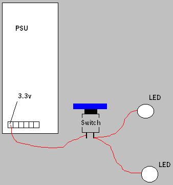
But wait, I've got 2 LED's
I've got 2 LED's...Whah Whah, Goo Goo! OK! Just solder the pos. wire already going to your pos. leg on the other LED to the same pos. current coming from the switch. Here's a diagram...
It's alive! It's ALIVE! :
Got it working? You turn the system on, and when you press the switch, both LED's go off, then you release and the LED's come on? Great. Your done! Ohh wait, you gotta mount the switch so it will work.
Mounting the LED(s) :
Ok, all you gotta do is figure out where you wanna put your LED(s). Try to stay away from the part on the inside thats level with the laser spindle. Thats where we wanna put the switch. All you gotta do is start with a small drill bit, and make your way up one size at a time until the LED fits snuggly. Once they're in, glue them in with your super glue from the bottom so it doesn't show. Now were ready for the switch...
Mounting the switch :
My switch was cool. All I had to do was drill a whole big enough for the switch to fit in, then place the nut on top. Hold the nut on the top with wrench, and tighten the nut on the bottom so you don't scratch the plastic on top, and have it look stupid. BUT! We have to find a place to put the switch.
Look at the inside. On the right part thats level witht he spindle is where we wanna drill for a switch. Look at the pic. You'll wanna position the switch as far over as possible. NOTE: You might drill a little bit into the side of the modem housing. BUT, you shouldn't end up drilling where it will show from the outside if the modem was removed.

If you don't go far enough out,when a CD is put in, it may scratch against the switch, OR even scratch up against the nut that holds the switch in place. Be careful! Once you got your switch mounted in, super glue it from the bottom for support. The CD door presses pretty hard here. Not THAT hard, but hard enough. Test this baby out!
It's working! Yes! :
Congrats! You successfully followed one of my tutorials! Good for you. Your the first! Probably not, but still, you did it! Good job. Sumbit a digi pic of your version of this mod to me using the e-mail link at the bottom!
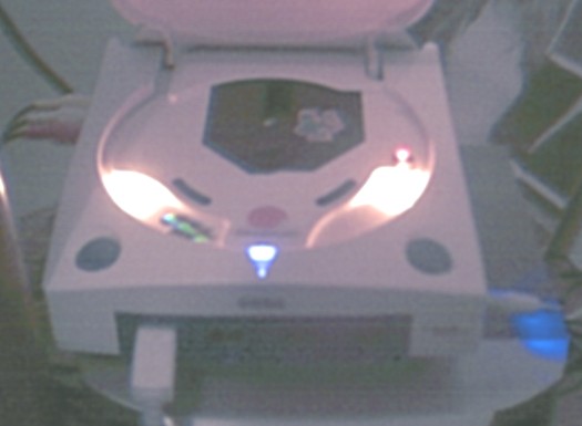
Here's my night light! :
The mofo didn't work! :
1. Check all solder points.
2. Make sure you don't have pos. and neg. wires mixed. Either on PSU or the LED(s).
3. Is the switch working properly? Test it with something.
4. Do the LED's work? Maybe only one LED came on,a nd the other didn't. Make sure the wries aren't reverse, OR the pos and neg. are correct.
That didn't answer my problem! :
E-mail me with your question regarding this mod with the subject line reading: Night Light Mod for DC Question at...
synthetic_ky@hotmail.com
For more information visit: http://djky2k3.tripod.com/
|