This is how I used a Mad Catz six-button controller as a host for other controllers and the modification of a NES pad to work with it.
Mad Catz (Host Controller):
I started with the Mad Catz controller, a NES pad, and a joystick extension cable (15 pin). The cable I used was made by Belkin and bought at Best Buy.
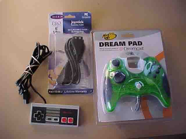
Remove the six rear screws holding the back cover of the Mad Catz and carefully remove the back cover.
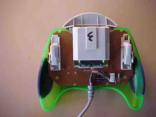
Remove the two screws at the top of the VMU slots and remove the circuit board assembly.
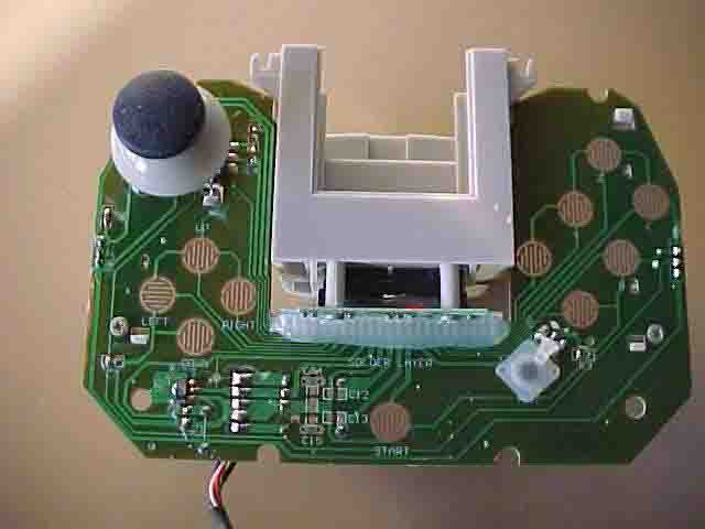
This board is very different from the first one that I modified, but the method is pretty much the same. There are eleven buttons on the board that I used: up, down, left, right, start, A, B, C, X, Y, and Z. The commands for these buttons are active when the depressed button connects their two contacts together. One contact is a ground that they all share in common, and the other is a contact unique to each button.
All of the contacts run to the solder connections underneath the silicone strip. This strip was then removed.
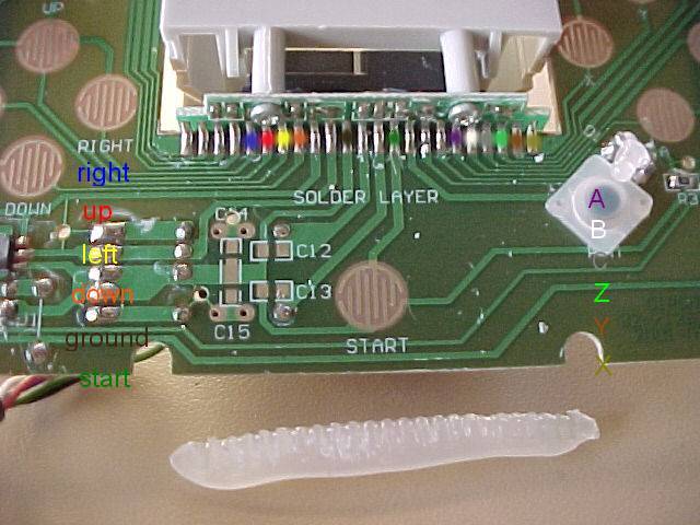
Using a multimeter, I determined which solder points were assigned to which buttons. From left to right: right=5 up=6 left=7 down=8 ground=11 start=14 A=18 B=19 C=20 Z=21 Y=22 X=23
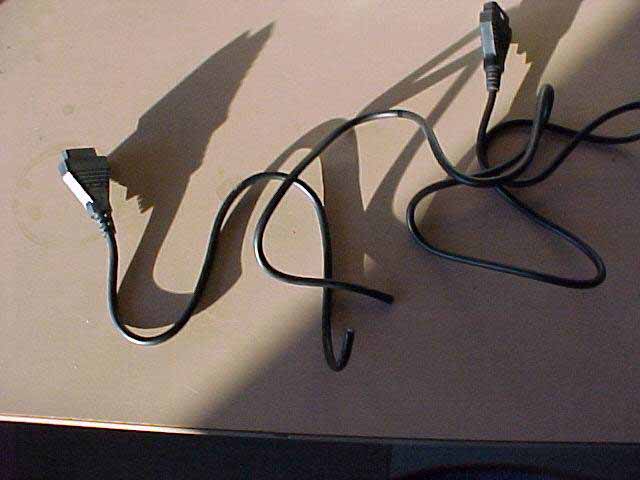
The next step is to cut the joystick extension cable. I cut about one foot from the female end, leaving about five feet on the male.
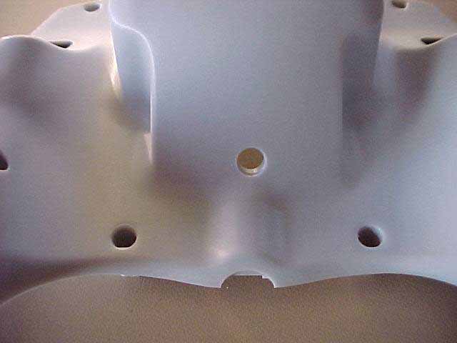
Then I drilled a hole in the back shell of the controller just big enough to feed the cut end of the cable through.
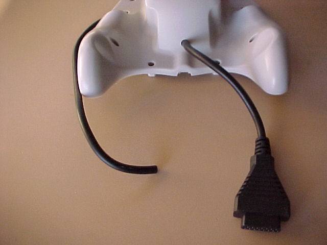
Next I fed the shorter (female) cable through the hole as shown:
After that I stripped the insulation off the cut end, exposing the fifteen wires, and tinned the ends of all fifteen.

With the multimeter I determined which color wire corresponded with which pin of the connector. For this cable (AND THIS IS ONLY FOR THIS CABLE-DIFFERENT MANUFACTURERS WILL BE DIFFERENT) the pins are wired as follows: 1=brown 2=red 3=orange 4=yellow 5=blue 6=green 7=violet 8=white 9=gray 10=yellow w/ black stripe 11=orange w/ black stripe 12=light green 13=light blue 14=pink 15=black.
I took the first six wires (1-6) and fed them through the gap at the left of the solder points. The next six wires (7-12) were fed to the right of the solder points.
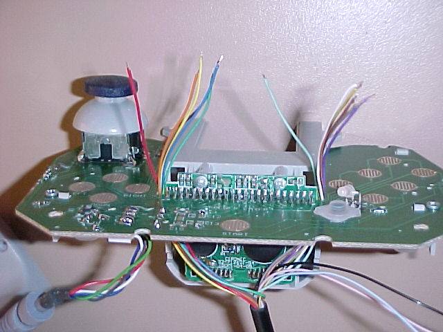
The first six were soldered in this order: ground up down left right start.
Which are pins: 11 6 8 7 5 14.
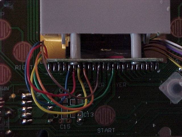
The next six were soldered in this order: A B C X Y Z.
Which are pins: 18 19 20 23 22 21.
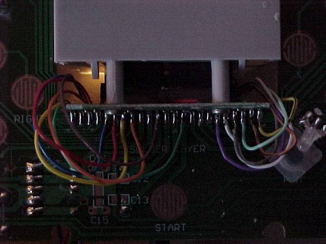
At this point check all of your connections carefully with a meter. Make sure no pins are shorted together and your connections are solid. A short in the wrong place will destroy your controller ports! If you have silicone sealant, it would be a good idea to replace what was removed and let it dry before continuing. Then carefully replace the board into the front shell with the two screws at the top. Be sure that the buttons and their pads are positioned correctly, and that none of the new wires are pinched by the case.
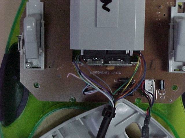
I put a zip-tie on the end of the cable housing (see above) that will keep the cable from being pulled out of the hole and provide strain relief. Carefully pull the slack cable through the hole and replace the back shell with the six screws. Again, be careful not to pinch any wires. I used a long thin tool to guide them as I closed the case.
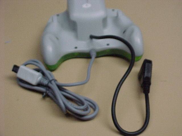

The host controller is now complete.
For the NES pad:
Remove the six screws in back of the unit and take off the rear case half. Then remove the board inside.
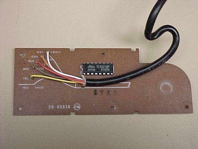
Then I removed the existing cable and the IC from the board. The IC must be removed, and the same theory goes for any other controllers used for this modification. Introducing circuitry into the Mad Catz circuit can cause damage to it or to your Dreamcast. Only the buttons are needed for this to work.
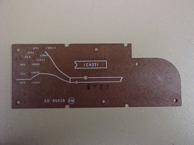
Using the same method as before, I determined which button contacts corresponded to which IC solder points. There are sixteen IC solder points, and from the front they are numbered as shown:
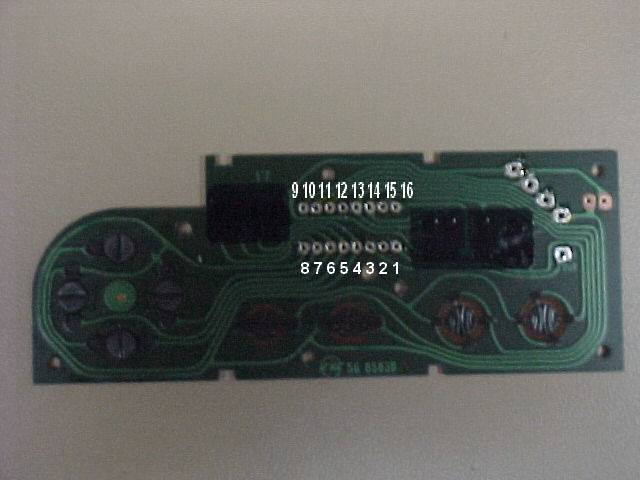
The buttons mapped out like this: ground=8 up=4 down=5 left=6 right=7 start=13 A=1 B=15 select=14.
The remaining long part of the joystick extension cable (male) was then stripped and the leads tinned the same way as before. Referring to the notes from earlier, I soldered to appropriate wires to the NES board. The cable pin 1 wire (brown) is ground on the Mad Catz, so I connected it to the NES pad's ground (solder point 8).
Ground cable pin 1 (brown) to NES 8
Up cable pin 2 (red) to NES 4
Down cable pin 3 (orange) to NES 5
Left cable pin 4 (yellow) to NES 6
Right cable pin 5 (blue) to NES 7
Start cable pin 6 (green) to NES 13
A cable pin 7 (violet) to NES 1
X (Nester's B) cable pin 10 (yellow w/ black) to NES 15
Y (Nester's Select) cable pin 11 to NES 14
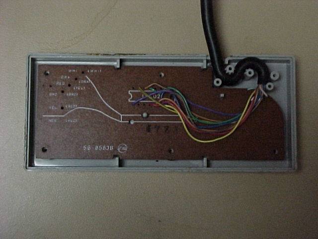
It should look like this:
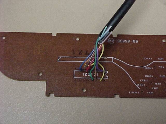
Then I again checked my connections with a meter to ensure that nothing was improperly shorted. After that I put the board back onto the front case half. I stripped enough the insulation off the cable to allow me to lay the cable in the pad as shown here:
After that, I replaced the back case with the six screws and plugged everything together. Nester is even better with the correct controller!
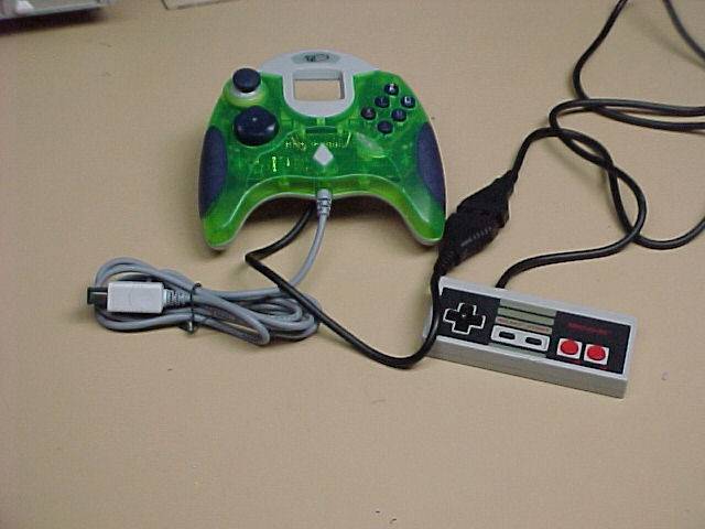
The NES pad is now ruined for anything but this use, but it was a $2 purchase just for this, anyway. The Mad Catz controller still will function fine on its own, it just has a new cable sticking out of it.
-Ted
|
