Three parts to the internal VGA modification:
1: Build a small vga circuit
2: Mount the vga connector, mode switch, and audio out jack
3: Wire the circuit and connectors
I am going to skip basics of soldering and disassembly of the Dreamcast. There are a lot of tutorials that already cover this. I also think that a mod like this requires some degree of proficiency in soldering and a basic understanding of electronics to attempt.
I built the circuit using the following schematic, keeping in mind that I need to assemble it a small as possible.
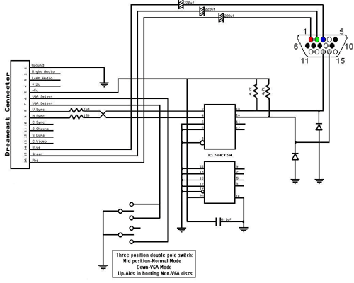
(Click Image to enlarge)
The circuit was not too difficult to keep small, consisting of one IC, four caps, four resistors and two diodes. I built the circuit as small as I could, attached the needed wiring, and insulated it with heat-shrink.
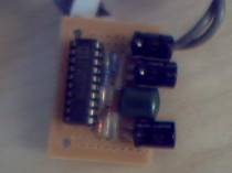 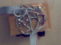
I have seen VGA cables for the Dreamcast for sale that may be small enough to use for this mod. I have not had my hands on one to see how small it actually is, but it could work. Levelsix.com sells one: http://www.levelsix.com/detail.aspx?ID=33
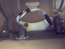
Mounting the VGA connector, switch, and audio jack was not too difficult. I bought all three at a local Radio Shack. The VGA connector was for a cable termination, I just discarded the shell. The 1/8” stereo jack was the smallest one that I could find that was threaded for mounting. The switch is the smallest three position double pole that I found. Used an exacto type razor knife to cut out the hole for the VGA jack and the switch. It was a bit if a slow process whittling through the plastic, but it did the job. Just try to make the hole as small as you think will work. It is easy to cut out a little more to make a snug fit, but going too big will ruin the neat mounting. I used a drill to make the two screw holes for mounting the VGA jack and for the line out jack. These pics show where I decided to place the three items:
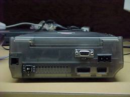 
 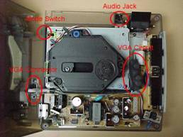
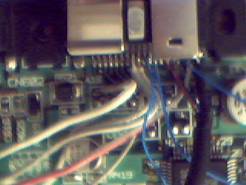
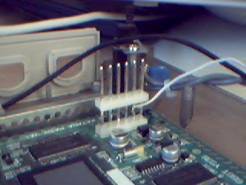
The next step was to make all of the connections between the A/V port, the VGA circuit, the VGA connector, the switch, the 1/8” jack, and the power supply.
All but one of my wires follows the schematic above. I chose to draw the 5VDC from the power supply board instead of the A/V port. The contacts are fairly close together and I wanted to avoid any chance of shorting out the power. Here are a few pics:
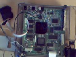
As shown in one of the earlier pics, I put an inline connector in the VGA jack's wiring to the VGA circuit. Since I mounted the jack to the top half of the Dreamcast's case, I wanted to still be able to remove the top if ever needed.
At this point I reassembled the unit, placing the VGA circuit between the CD drive and the controller board. Use cares to make sure that no wires are crimped or get in the way of the console's operation.
The unit was then completed. The VGA and TV positions of the switch are self-explanatory. The position that I labeled MOD can help to boot up non-VGA games. By grounding pin 7, but not pin 6 the console will boot up in a “halfway VGA” mode. When you power up the console you will hear the Dreamcast sound where the orange swirl pops up. A few seconds after that, switch to the VGA position. If timed correctly it will force the console in VGA mode even if the game does not support it. It works with most of these non-VGA games, but not all.
I know that this is not the best of tutorials, but I hope that it gives an overview of what I did to install the internal VGA adapter. If I were to ever do a similar mod again, I would try using the pre-made circuit out of the VGA cable that I mentioned, and document it as I went along to write a true tutorial.
-Ted
|
